CAN BUS Netwoking for Electric Vehicle
“CAN Bus Networking Based on Arduino Embedded Platform”
CAN – Controller Area Network bus is widely used in Automobile industry and in other industrial applications.
CAN
is like Nervous system in Human body facilitating communication between all
parts of body.
In
CARs , NODEs or ECUs – Electronic Control Units are connected via CAN bus which
acts as a control nervous system.
ECUs can be Engine control unit, Airbag control, Audi
System , Door position,Brake system, Sensors & others.Each and every
function can be assigned a NODE or ECU.
A
modern CAR has upto 100 ECUs.

CAN allows ECUs to communicate with each other
without complex dedicated wiring in between. Any ECU can communicate with
entire system without causing overload to the controller computer.

CAN
is MULTI MASTER setup. Any Node can be a MASTER.
CAN
works on a MESSAGING TYPE SYSTEM & no slave address is used to
communicate with a node.
Every
Node receives the message and the related data will be conceived by the
receiver node.
It
is like public announcement system in an Airport Only concerned passengers will
take the message.
To
balance the CAN BUS and for noise reduction a 120E RESISTOR is used as
Terminator. This is must for END NODES. Nodes added in between need not use
this Resistor.
In
this project we make use of a CAN Board CAN2515.
This
board has 2 ICs. One is the CAN Controller MCP2515 , which communicates
with Arduino or any MCU by SPI Protocol.
MCP2515
gives SINGLE ENDED DIGITAL signal (High ,Low).
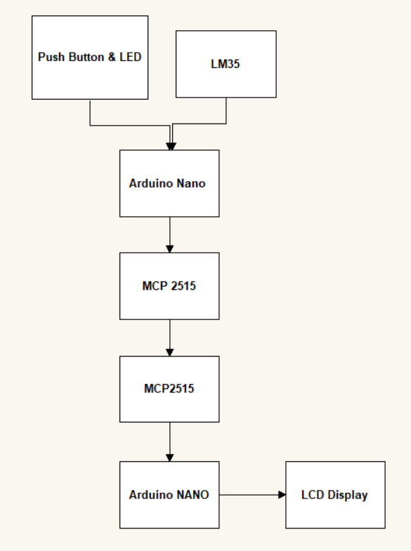
MCP2515

Communication Between Two Arduino through CAN Bus Network

Connection
of Pins Between Two Arduino & MCP2515
|
Arduino Pin |
MCP2515 Pin |
|
D13 |
SCK |
|
D12 |
SO |
|
D11 |
SI |
|
D10 |
CS |
|
VCC |
VCC |
|
GND |
GND |
LCD Display

An LCD (Liquid Crystal Display) screen is
an electronic display module and has a wide range of applications. A 16x2 LCD
display is very basic module and is very commonly used in various devices and
circuits. A 16x2 LCD means it can display 16 characters per line and there are
2 such lines. In this LCD each character is displayed in 5x7 pixel matrix. The
16 x 2 intelligent alphanumeric dot matrix display is capable of displaying 224
different characters and symbols. This LCD has two registers, namely, Command
and Data.
Command register stores various commands
given to the display. Data register stores data to be displayed. The process of
controlling the display involves putting the data that form the image of what
you want to display into the data registers, then putting instructions in the
instruction register. In your arduino project Liquid Crystal
Library simplifies this for you so you don't need to know the low-level
instructions. Contrast of the display can be adjusted by adjusting the potentiometer
to be connected across VEE pin.
On 16 * 2 we are monitoring Temperature
of surrounding , Vehicle door is open or closed based on the status of Led.
Connection
of Pins Between Arduino & LCD
Display

Connection
Between Arduino & LM35

LM 35 Pin |
Arduino Pin |
|
Vcc Pin |
+5V |
|
Ground Pin |
GND |
|
Analog Pin |
A0 |

Connection & Actual
Circuit diagram of CAN BUS Communication Between Two Arduino

Programming for CAN BUS Commination
Arduino NANO 1 (Transmitter) Program –
#include <SPI.h>
#include
<mcp2515.h>
struct can_frame
canMsg1;
MCP2515 mcp2515(10);
int btn_stat = 0;
int tmp_val_raw;
float tmp;
void setup()
{
while (!Serial);
Serial.begin(115200);
mcp2515.reset();
mcp2515.setBitrate(CAN_125KBPS);
mcp2515.setNormalMode();
pinMode(2,OUTPUT);//LED
pinMode(3,INPUT);//Button
pinMode(A0,INPUT);//LM35
}
void loop()
{
read_tmp();//function for reading temperature
data
msg_create();//funcion for creating CAN
message with i/p sensor value
mcp2515.sendMessage(&canMsg1);
Serial.println("Messages sent");
delay(100);
}
void read_tmp()
{
tmp_val_raw = analogRead(A0);
tmp=((tmp_val_raw*330.0)/1024.0);
//Serial.print("Temperature(LM35):");
//Serial.println(tmp);
}
void msg_create()
{
btn_stat = digitalRead(3);
digitalWrite(2,btn_stat);
canMsg1.can_id = 0x0F6;
canMsg1.can_dlc = 8;
canMsg1.data[0] = btn_stat;
canMsg1.data[1] = tmp;
canMsg1.data[2] = 0x00;
canMsg1.data[3] = 0x00;
canMsg1.data[4] = 0x00;
canMsg1.data[5] = 0x00;
canMsg1.data[6] = 0x00;
canMsg1.data[7] = 0x00;
}
Arduino NANO 2 (Receiver) Program –
include <SPI.h>
#include
<mcp2515.h>
#include <LiquidCrystal.h>
struct can_frame canMsg;
MCP2515 mcp2515(10);
const int rs = 2, en =
3, d4 = 4, d5 = 5, d6 = 6, d7 = 7;
LiquidCrystal lcd(rs,
en, d4, d5, d6, d7);
void setup() {
Serial.begin(115200);
lcd.begin(16, 2);
mcp2515.reset();
mcp2515.setBitrate(CAN_125KBPS);
mcp2515.setNormalMode();
}
void loop() {
if (mcp2515.readMessage(&canMsg) ==
MCP2515::ERROR_OK)
{
int door_stat = canMsg.data[0];
int temp = canMsg.data[1];
lcd.clear();
lcd.setCursor(0,0);
lcd.print("**CAN_BUS Comm**");
lcd.setCursor(0,1);
lcd.print("Door:");
if(door_stat)
{
lcd.print("Open");
}
else
{
lcd.print("Close");
}
lcd.setCursor(10,1);//setcursor(col,row);
lcd.print("Tmp:");
lcd.print(temp);
}
Result
1. When LED is OFF – (Indicates vehicle door is close)

2. When LED is ON - – (Indicates vehicle door is Open)

Demo of CAN Bus Model -
I would like to be thankful to all the
people who are involved directly or indirectly in the completion of my
PGDEM Project. First and foremost I would like to express my
grateful thanks to my advisor Dr. Y. K. Bhateshvar sir for his
encouragement and guidance throughout my PGDEM program.
I would like
to thank Dr. Dhananjay Kumar sir for providing valuable ideas
and support towards completion of my PGDEM Project. I would like
to thank Dr. K. C. Vora sir for providing me path to study at ARAI FID,
chakan & Due to him only I learn many practical things
at ARAI FID.ARAI FID decrease gap between industrial requirements
& Educational System by practical approach based teaching
which is require by industries.
Also I would like to thanks to S. R.
Sayyed sir (TPO, ARAI FID) & Aditya Sonawane (Placement
Co-ordinater).As provide me chance to work in industry. Last but not
the least, I would like to thank my parents, family and friends for
providing me all kind of support to achieve my PGDEM Program.
References:
- G. Leen and D. Heffernan,
"Expanding Automotive Electronic Systems," IEEE, pp.88-93, 2002.
- P. Furmanski and Z. Stolarski,
"Controller Area Network Implementation in Microwave Systems,"
in Microwaves, Radar and Wireless Communications, 2002. MIKON2002. 14th
international conference, vol. 3, 2002, pp. 869-873.
- https://www.seeedstudio.com/blog/2019/11/27/introduction-to-can-bus-and-how-to-use-it-with-arduino/
- https://circuitdigest.com/microcontroller-projects/arduino-can-tutorial-interfacing-mcp2515-can-bus-module-with-arduino.
Comments
Post a Comment